


In vivo calcium imaging enables scientists to visualize hundreds of neurons in the brain of freely-behaving animals. In this guide, we will explore the key questions related to performing in vivo calcium imaging.
In Vivo Calcium Imaging
The brain contains over a billion neurons, each with complex networks of connections. Patterns of neural activity are believed to generate specific aspects of behaviour and cognition, but how can this be addressed?
Current techniques, such as in vivo electrophysiology, can record neural activity with spike-timed precision, but they cannot localize the activity of large populations of individual cells or identify cell types
To decode patterns of neural activity, neuroscientists need to visualize hundreds of neurons simultaneously—not just an individual neuron—in freely-behaving animals. From a technology standpoint, this is no easy feat.
How can you visualize neural activity in vivo?
Calcium Imaging
Calcium imaging enables neuroscientists to visualize the activity of hundreds of individual neurons simultaneously using fluorescent activity sensors. Changes in fluorescence indicate fluctuations in intracellular calcium, which is an indirect indicator of neural activity (Grienberger & Konnerth, 2012).
The development of genetically encoded calcium indicators (GECIs) has enabled neuroscientists to study specific cell types (e.g., excitatory or inhibitory neurons).
GCaMP, a green fluorescent GECI, is commonly used in calcium imaging experiments since it has been optimized over many generations (currently GCaMP7) for speed, signal-to-noise ratio, expression, and changes in fluorescence (Dana et al. 2012). The calcium imaging toolbox is growing constantly with the development of new GECIs, such as RCaMP and XCaMP (Akerboom et al. 2013; Inoue et al. 2019).

GECIs, such as GCaMP, are expressed in specific cells (in green). Changes in activity are only detected in cells expressing the GECI.
Recently, there has been a surge in the use of calcium imaging to study neural circuits in vivo. This popularity has led to both optimized biological methods and better optical technologies, allowing more neuroscientists to adopt calcium imaging.
Aside from popularity, why are neuroscientists drawn to calcium imaging?
In vivo calcium imaging provides the means to study specific populations of neurons within or across brain regions in freely-behaving animals. Thus, neuroscientists can investigate how neural activity may be linked to aspects of behaviour and cognition, connecting genetically-identified cells with function.
Importantly, behaviour and cognition cannot be characterized by an isolated firing pattern of neurons because they are learned or adapted over time. Calcium imaging can be used to track the activity of neurons over time and investigate how networks grow or change during learning. This is especially important for the longitudinal study of animal models. Neuroscientists can begin to understand the development of activity-related changes in these models and assess the long-term effects of pharmacological interventions.
With any new technique, there are associated pitfalls. As we’ve known for years, neural activity is associated with action potentials—changes in voltage across the cell membrane. Calcium imaging measures changes in intracellular calcium concentrations, providing an indirect indicator of neural activity. Compared to changes in voltage, fluctuations in calcium levels are much slower and may reflect a summation of signals rather than individual spikes (Wei et al. 2019). That is to say, the temporal resolution of calcium imaging may be limited for fast-spiking neurons, such as interneurons.
The gradual development of genetically encoded voltage indicators (GEVIs), designed to detect changes in voltage, is expected to overcome these limitations (Knopfel & Song, 2019). As with any new technology, widespread application of GEVIs will take time, requiring validation and optimization for use in vivo.
Despite this limitation, in vivo calcium imaging has been able to advance our understanding of how neural activity is linked to behaviour and cognition.
If someone were to describe in vivo calcium imaging to you, it might sound quite simple.
When you dig deeper, you start to appreciate the complexity associated with the biology and equipment required to perform calcium imaging in freely-behaving animals.
You’re probably asking, what is needed to perform in vivo calcium imaging?
Biological Components
Brains don’t naturally express genetically encoded calcium indicators (GECIs), meaning there are biological steps needed to perform calcium imaging in freely-behaving animals.
First, you must express the genetic indicator in the brain. Second, you need to implant an imaging probe to collect fluorescent signals from the brain.
Genetic Sensor Expression
The first step, and most important, is achieving optimal GECI expression in your animal model.
Mice are the most common animal model used for in vivo calcium imaging due to the advancement of genetic mice models (Daigle et al. 2018); however, calcium imaging has slowly progressed in rats and non-human primates (Scott et al. 2018; Kondo 2018).
Neuroscientists employ two methods to express GECIs in the brain: viral expression and transgenic animal models.
Viral expression involves injecting a virus encoding a GECI in the brain. This virus is linked to a gene of interest, targeting expression to a specific cell-type.
A crucial step associated with viral expression is testing varying dilutions of the virus to obtain optimal expression in the brain (Resendez et al. 2016). Too little expression can lead to no signal, and over-expression can lead to high background fluorescence–or even cell death!
Neuroscientists employ viral expression to regulate GECI expression. This technique is useful because expression can vary depending on the brain region, cell-type, or virus. Also, viral expression can be used to express GECIs in brain projections to map neural circuits across brain regions.
In comparison to manual viral injections, transgenic animal models are designed to express the GECI throughout the entire brain (Dana et al. 2014). Depending on the transgenic model, GECI expression can vary from region to region, such that one region may express the GECI more than another. Neuroscientists examining large cortical areas use these models as they require much more widespread expression, rather than a single region of interest (Dana et al. 2014).

GECIs can be expressed through viral expression (on the left), and this limits expression to a specific cell-type and brain region. In comparison, transgenic expression (on the right) is widespread throughout the brain.
After successful GECI expression, you need to access the fluorescent signal inside the brain. But how can you see into the brain when it’s covered by both skin and skull?
Generally, this involves surgically implanting an imaging probe into the brain where the GECI is expressed to visualize activity. There are three types of probes (optical cannula, cortical window, GRIN lens) that are used for in vivo calcium imaging. The probe you select is dependent on two main factors:
- Do you require cellular-resolution imaging?
- Will you be imaging a deep or superficial brain region?
Optical cannulas enable light to be delivered and collected from the brain. These probes are used in fiber photometry experiments. Due to their design, optical cannulas are only capable of collecting one signal or a population signal, providing no spatial resolution to image individual neurons. Depending on the length of the optical cannula, they can be used to collect a fiber photometry signal from shallow or deep brain regions. Another bonus is optical cannulas are the least invasive to be implanted in the brain because of their compact design, which leads to minimal tissue damage.
In contrast, cortical windows replace a large portion of the skull with a glass window. Neuroscientists employ cortical windows when imaging a large cortical region on the surface of the brain or the entire cortex. Cortical windows can provide access to the cortex for cellular-resolution or large-scale calcium imaging recordings.
Lastly, a GRIN lens is a microendoscopic probe that can be implanted in the brain to image individual neurons. GRIN lenses differ in lengths, enabling neuroscientists to image shallow to deep brain regions (up to 8mm). GRIN lenses are typically limited in diameter (0.5–1mm). Thus, imaging with GRIN lenses provides a relatively small field of view, compared to cortical windows, and the implantation of a large GRIN lens can lead to tissue damage, compared to an optical cannula. However, a GRIN lens is the only imaging probe available to image with cellular-resolution in the brain of a freely-behaving animal.

The implantation of a GRIN lens (on the left) enables the visualization of individual neuron activity. In comparison, implantation of an optical cannula (on the right) provides no cellular-resolution and enables visualization of population activity.
Equipment Components
Now that you have all your biological components set up, you need equipment to record fluorescent signals from the brain of a freely-behaving animal.
The systems currently available for in vivo calcium imaging are comprised of three main components:
- Coupling between the imaging probe and imaging device
- Light source and filter set
- Imaging device

Most in vivo calcium imaging systems are comprised of the following components: 1) imaging probe, 2) coupling between the light source and imaging probe, 3) light source, 4) filter set, and 5) imaging device.
Coupling Between Imaging Probe and Imaging Device
Fluorescent signals are emitted from neurons expressing the GECI, and this is transmitted through the imaging probe. But how can data be collected?
First, you need a coupling between the imaging probe, light source, and imaging device. This coupling enables the GECI to be illuminated in the brain through the imaging probe, and subsequently, the transmission of the emitting fluorescent signal is sent to the camera. Depending on the calcium imaging system design, this coupling may be achieved via an imaging fiber, optical fiber, or the system may be directly mounted onto the head of the animal, such as the miniscope.
Light Source and Filter Set
GECIs generate fluorescence signals, such that they have an excitation and emission spectrum (Grienberger & Konnerth 2012). To excite GECIs and filter the emitted signal, you require two components: a light source and dichroics/filters.
LED light sources are commonly selected for in vivo calcium imaging since low optical power is required. However, if a larger region of interest is being illuminated, a high-power laser may be required. There is a balance between too little and too much power: not getting enough signal and photobleaching your sample, respectively.
Importantly, the correct excitation wavelength must be selected. For example, GCaMP excitation is blue (~470nm) and emission is green (~530nm).
And this is where the second component is necessary. Dichroics and filters allow for the transmission of the correct excitation and emission wavelength to the imaging device.
Imaging Device
Lastly, you need to collect and analyze fluorescent signals from the brain. This is made possible using an imaging device.
Three types of imaging devices are used for in vivo imaging systems: 1) scientific camera, 2) PMT, and 3) photodetector. The imaging device used is somewhat dependent on the calcium imaging system. If you’re interested in learning more about the differences between imaging devices, this is a helpful article.
Successful in vivo calcium imaging is a balancing act between biology and equipment. Luckily, both the biology and equipment are constantly being optimized for better performance and ease of use, making the technique more accessible to labs worldwide.
A long-standing objective in neuroscience has been elucidating how in vivo neural activity relates to sensory processing, behaviour, cognition, and cortical processing. Researchers have attempted to understand this relationship by developing a wide range of all-optical tools for calcium imaging in freely-moving animals.
The requirements for in vivo calcium imaging vary depending on the imaging resolution, animal model, field of view, data collection, and brain region. With a varying degree of requirements, there are different calcium imaging systems available to decode the complex connection between brain activity and function.
What systems are available for in vivo calcium imaging?
1. Fiber Photometry
Fiber photometry is an in vivo calcium imaging method that detects average fluorescence intensity changes. Thus, this method is used to measure population neural activity in a freely-behaving animal (Cui et al. 2014). With an implanted optical cannula coupled to an optical fiber, light is delivered and retrieved from the brain. The acquired signal is then collected by an externally positioned imaging device (photodetector, PMT, or camera).
Fiber photometry data acquisition is limited to population-level activity with no cellular resolution to visualize individual neurons. However, the benefit of low cellular resolution is small data files, fast acquisition, and easy data interpretation, unlike other current calcium imaging tools. Thus, fiber photometry provides a low entry barrier for new labs wanting to adopt calcium imaging or perform exploratory research.
The light-weight design and less invasive surgeries make it possible to perform fiber photometry in multiple brain regions simultaneously. Multi-region fiber photometry is performed using a multi-fiber patch cord and imaged onto a camera for data acquisition (Kim et al. 2016). In comparison, a single region fiber photometry experiment uses a single patch cord, and the signal is captured using a photodetector or PMT.
The light-weight equipment required for fiber photometry helps to extend the length of experiments and reduce extraneous factors (e.g. stress), allowing for more natural animal behavior to be observed during experiments. Also, certain systems can be used with a rotary joint for freely-behaving experiments.
Fiber photometry is a useful tool that can provide us with a better understanding of low-level circuitry in the brain. The simplistic design and data output of this tool provide a good starting point for in vivo calcium imaging.

A standard fiber photometry setup.
2. Miniscope
A miniscope is a miniaturized microscope that mounts on the head of an animal to image neural activity in a freely-behaving animal (Ghosh et al. 2011). By coupling a miniscope to an implanted GRIN lens (deep brain) or a cortical window (cortex), you can image large populations of individual neurons in a freely-behaving animal. The design of a miniscope is essentially the same as a one-photon microscope, consisting of the appropriate lenses, LED, filters, and camera.
The development of the miniscope unlocked the ability to image the activity of thousands of individual neurons in freely-behaving animals (Ghosh et al. 2011). The ability to imagine in freely-behaving animals is supported by the miniaturization of the miniscope that has all the components integrated (~2g) into one system. The minscope provides a field of view that is determined by the size of the implanted GRIN lens (ranging from 0.5 to 1mm diameter), and the selection of the GRIN lens will depend on the region of interest.
Recent developments in miniscope technology have enabled researchers to perform dual-colour imaging, wireless calcium imaging, and two-photon calcium imaging in freely-behaving animals (Zong et al. 2017; Shuman et al. 2020).
With a miniaturized design and all components being integrated on the head of the animal, the miniscope allows the animal to behave freely, but it also partially constrains the possible integrated components. These include low-level cameras with low sensitivity and high noise that are not capable of high-resolution imaging, and the number of wavelengths they can illuminate is currently restricted to one or two. Thus, the capabilities of this system and the flexibility for future updates are currently limited.
Miniscopes have advanced our understanding of neural activity. This system can provide further insight into the activity of large neural populations with calcium imaging in freely-behaving animals.

A standard miniscope setup.
3. Optical Fiberscope
The optical fiberscope, such as Mightex’s OASIS Fiberscope, is an all-optical system that enables cellular-resolution calcium imaging in freely-behaving animals using an imaging fiber. A removable imaging fiber, coupled with a GRIN lens implanted in the brain or cortical window, provides calcium imaging in the deep brain, cortex, or spinal cord of a freely-behaving animal.
The imaging fiber consists of thousands of individual micro-fibers, enabling the imaging of individual neurons in freely-behaving animals. An optical fiberscope can also be used to perform population-level imaging, identical to fiber photometry. This enables researchers to begin experiments with fiber photometry and later delve deeper using cellular-resolution calcium imaging. Like a miniscope, the optical fiberscope’s field of view is determined by the size of the implanted GRIN lens.
A wide range of calcium imaging applications can be executed with the optical fiberscope, such as dual-colour imaging and multi-region calcium imaging. The optical fiberscope is the only system that can image multiple brain regions with cellular-resolution—to view individual cells—in a freely-behaving animal.
The weight of the flexible imaging fiber and the head-mounted fixture is very low (as little as 0.7g). And, all the electronics are located off the head of the animal, compared to the miniscope. Thus, the length of experiments can be extended and extraneous factors (e.g., stress) can be reduced, allowing for more natural animal behavior to be observed with the optical fiberscope. To add to this, the recent implementation of an intricate rotary system enables better freely-behaving experiments with the optical fiberscope.
A vital benefit of the optical fiberscope is the unique flexible design. This system is scalable and reconfigurable, making it a generic calcium imaging and stimulation platform that can be adapted for different applications, unlike many other single-purpose systems. Two illumination paths allow researchers to attach multiple wide-field and/or targeted light sources with different wavelengths and to insert different optical filters (e.g., dichroics) suitable for different imaging and/or illumination needs. Also, this system is compatible with high-quality scientific cameras for capturing better quality images (e.g., with better signal-to-noise ratios and better linearity) for data analysis.
The optical fiberscope is a flexible tool designed to help understand how single-cell interactions are involved in advanced brain functions, which is not possible with other current technology.

A standard optical fiberscope setup.
System Comparison Table

The invention of optogenetics has enabled scientists to use light to turn cell-type specific neural activity on or off with millisecond-precision to probe neural circuit function. Complementing optogenetics, calcium imaging has provided scientists with a method to observe cell-type specific neural circuit activity with cellular-resolution using fluorescent indicators.
The integration of optogenetics and calcium imaging opens the door to these techniques being performed simultaneously in the same experiment to investigate the causal link between neural circuit activity, function, and behaviour. All-optical optogenetics and calcium imaging can enable scientists to image the activity of neurons in vivo and simultaneously perturb cellular activity using optogenetics in the same animal to both ‘read’ and ‘write’ neural activity.
To perform all-optical experiments with both calcium imaging and optogenetics, scientists require both optimized biology and advanced optical systems.
All-Optical Biology
Optogenetic probes have been developed with different functions (excitation or inhibition), activation times, and expression properties.
They are excited by wavelengths of light ranging from blue to red, depending on their properties. Channelrhodopsin (ChR2) has been the optogenetic tool of choice for excitation of neural activity and halorhodopsin for inhibition due to their extensive development and use in the field of optogenetics. Optogenetic probes have only an excitation spectrum to activate their excitation/inhibitory properties (Yizhar et al. 2011).
In contrast, GECIs behave in the same manner as a fluorophore (e.g., GFP), such that they exhibit excitation and emission spectra. However, the fluorescent signal of GECIs is dependent on intracellular calcium concentrations (i.e., increased fluorescence emission due to increased calcium influx) and displays dynamic behaviour, unlike a static signal emitted from a fluorophore (Grienberger & Konnerth 2012).
Researchers commonly propose the use of GCaMP for imaging and channelrhodopsin (ChR2) for optogenetics in all-optical experiments due to the optimization, efficiency, and frequent use of these biological probes.
However, a problem occurs with this combination: GCaMP and ChR2 have overlapping excitation spectrums (peak wavelength ~470nm). When GCaMP and ChR2 are expressed in the same tissue, calcium imaging light excitation can potentially activate the optogenetic probe as well. Thus, GCaMP imaging and ChR2 optogenetic stimulation cannot be performed simultaneously due to potential optical crosstalk. It is not possible to determine if measured changes in GCaMP signals are due to natural changes in neural activity or optogenetic-induced changes.

Overlap between the excitation spectra of GCaMP and ChR2.
Optical crosstalk in all-optical experiments can be reduced by selecting imaging indicators and optogenetic probes with non-overlapping excitation spectrums (Emiliani et al. 2015).
Examples of combinations with reduced optical crosstalk are blue excitation/green emission imaging (e.g. GCaMP) and red-shifted optogenetics (e.g. Chrimson, Jaws) or green excitation/red emission imaging (e.g. RCaMP) and blue-shifted optogenetics (e.g. ChR2, GtAChR). Although there may be some overlap between the excitation spectrums of these probes, the likelihood of crosstalk will be reduced, preventing indirect activation of your optogenetic construct during imaging.
The further optimization of imaging and optogenetics probes (e.g. sensitivity, excitation spectra) will help prevent optical crosstalk in all-optical optogenetics and calcium imaging experiments.

Separation of excitation spectra between GCaMP and red-shifted optogenetic constructs.
All-Optical Systems
1. Fiber Photometry
Optogenetics can be integrated into fiber photometry experiments. The only additional equipment required is the appropriate LED for optogenetic stimulation and filter set to combine with the calcium imaging LED. An example includes adding a red LED for red-shift optogenetics and GCaMP imaging (Kim et al. 2016).
Similar to calcium imaging with fiber photometry, optogenetic stimulation can only be performed widefield, stimulating all neurons with no cellular resolution.
A key feature of fiber photometry is the possibility to perform multi-region optogenetics in combination with multi-region calcium imaging; however, in this setup, due to technical limitations, optogenetic stimulation cannot be conducted in one select region at a time, and instead, it illuminates all regions simultaneously (Kim et al. 2016).
Fiber photometry is a simplistic method to perform population all-optical calcium imaging and optogenetics experiments in one or multiple brain regions.

Fiber photometry systems provide no cellular-resolution for calcium imaging or optogenetics.
2. Miniscope
Recently, miniscopes have integrated optogenetics (Stamatakis et al. 2018). This requires an additional LED and the appropriate filter set to collect the correct signal. Unlike fiber photometry, the LED and the filter are directly integrated into the miniscope (2~3g in weight), and this creates additional weight on the head of the animal.
Due to the inability of integrating a DMD pattern illuminator or a laser scanner, miniscopes are restricted to performing widefield optogenetics, with no cellular resolution. Miniscopes can be used to visualize individual neurons with cellular resolution, but they can only optogenetically stimulate all cells.
Also, miniscopes are limited to performing optogenetics and imaging in a single brain region due to the relatively bulky size and heavyweight of the system.

Miniscope systems provide cellular-resolution for calcium imaging but not for optogenetics.
3. Optical Fiberscope
Compared to the optical systems described above, an optical fiberscope (such as Mightex’s OASIS Fiberscope system) is an extremely flexible system for all-optical calcium imaging and optogenetics. This system can easily be upgraded with optogenetics capabilities by simply adding the appropriate LED and filter set combination.
In comparison to both the miniscope and fiber photometry, the optical fiberscope can not only perform widefield optogenetics but also, by integrating a digital-mirror-device (DMD), be used to perform cellular-resolution optogenetics in vivo. The optical fiberscope is the only freely-behaving system capable of cellular-resolution calcium imaging and cellular-resolution optogenetics in a freely-behaving animal. Scientists can perform these experiments in the deep-brain or across a large area of the cortex.
For larger field of view or higher-power applications, lasers (instead of LEDs) can be used for optogenetics using the optical fiberscope
Researchers can perform cellular-resolution calcium imaging and optogenetics in multiple regions simultaneously by using a split-fiber with the optical fiberscope. For example, one can stimulate multiple individual neurons or a selected group of neurons in one region and image individual cells in another, and this is not possible with fiber photometry or a miniscope.
The optical fiberscope is a powerful all-optical imaging and optogenetics system capable of both cellular-resolution optogenetics and cellular-resolution imaging in a single brain region or multiple brain regions simultaneously.

Optical fiberscope systems provide cellular-resolution for calcium imaging and optogenetics.
System Comparison Table

Freely-Behaving Calcium Imaging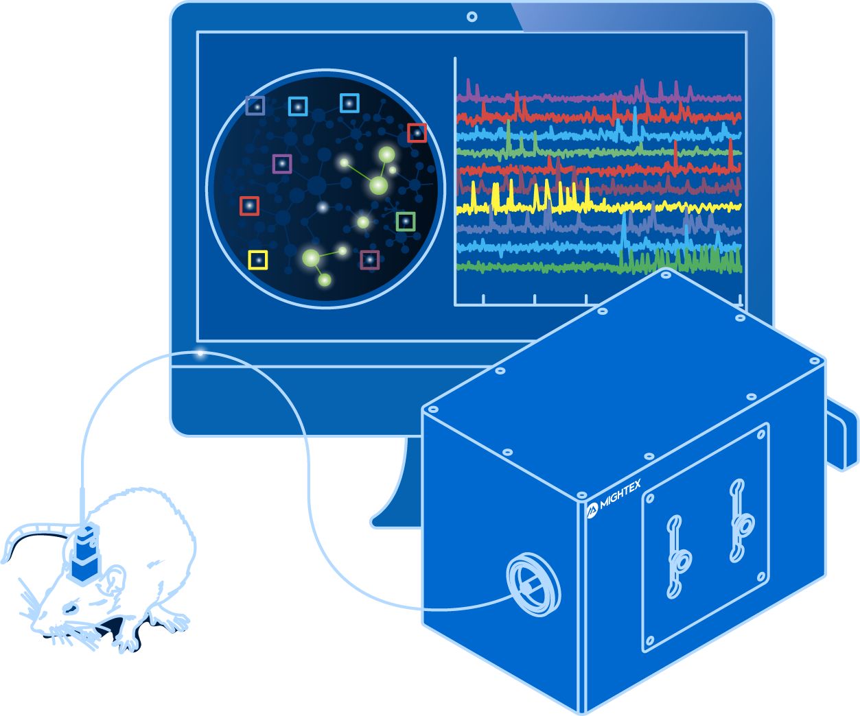
and optogenetics to probe complex neuronal networks.
for Cellular-Resolution Optogenetics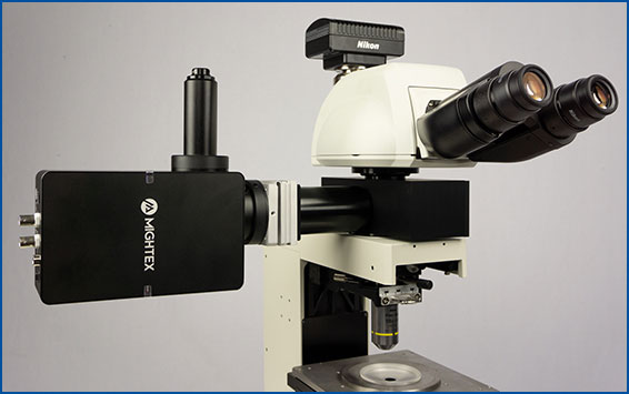
spatiotemporal control of light with subcellular resolution.