


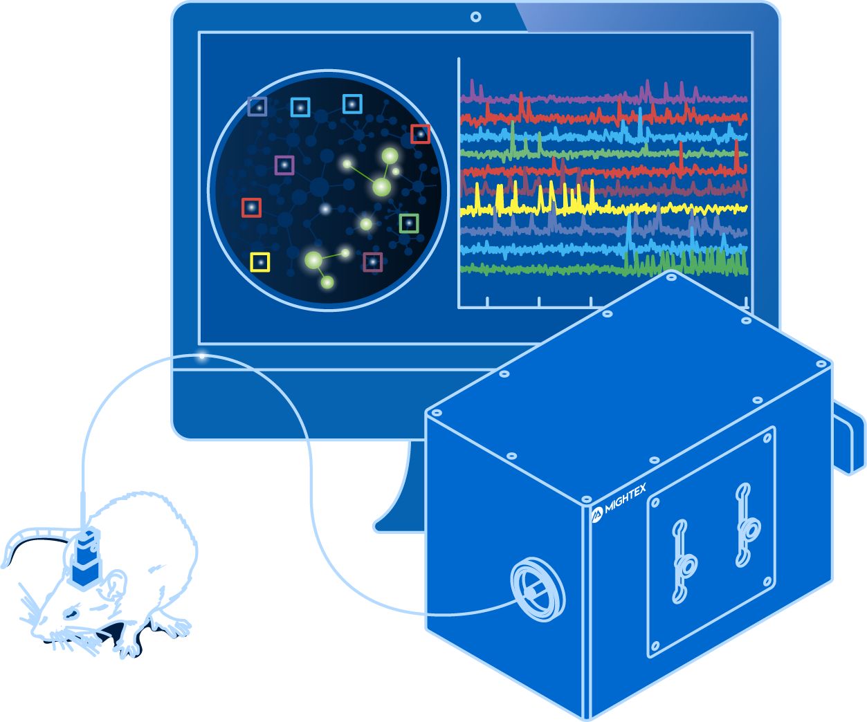
Fiber photometry is an imaging method that enables scientists to image population-level neural activity in the brain of freely-behaving animals.
This guide explores questions related to fiber photometry, including what is fiber photometry? What equipment is necessary for fiber photometry?
Calcium imaging enables neuroscientists to visualize the activity of large neuronal populations using fluorescent activity indicators (Grienberger & Konnerth, 2012). The invention of imaging technologies, such as the optical fiberscope or miniscope, allows for calcium imaging to be performed in freely-behaving animals with single-cell resolution (Ghosh et al. 2011). These capabilities enable neuroscientists to map the relationship between neural circuits and behaviour with single-cell resolution.
Despite many advantages, single-cell resolution calcium imaging systems are (1) more complex and generate large data sets that are difficult to handle, and (2) require more intricate surgical procedures. For labs just starting with calcium imaging or performing exploratory experiments, single-cell imaging may be too overwhelming or unnecessary.
Is there a simpler and less expensive technology for in vivo calcium imaging?
Fiber Photometry
What is Fiber Photometry?
Fiber photometry, as a technology, enables the measurement of population-level activity with calcium imaging (Gunaydin et al., 2014). Instead of visualizing individual neurons, the combined or ‘bulk’ activity signal from all neurons is measured from the neurons expressing the fluorescent activity indicators (Gunaydin et al., 2014), which leads to various benefits elaborated below.
The lack of cellular resolution with fiber photometry is due to a simplified coupling mechanism between the brain and the imaging device. With an optical fiberscope or miniscope, a GRIN lens is implanted into the brain and this enables an image with cellular resolution to be collected from the brain (Resendez et al. 2016). Thus, the changes in an individual neuron’s activity can be detected. In comparison, fiber photometry uses a low-cost implanted cannula that does not provide cellular resolution for imaging but rather collects a cumulative and combined signal from all neurons.

Why Use Fiber Photometry?
Fiber photometry has become a very popular method for in vivo calcium imaging due to its many advantages.
First, fiber photometry has a low entry barrier for labs wanting to integrate calcium imaging into their experiments. Compared to single-cell resolution imaging technologies, fiber photometry provides a much simpler data output, lower data output, and has a lower associated cost.
Second, from a technical and biological standpoint, fiber photometry is easier to implement, compared to other calcium imaging technologies. Due to the use of a cannula, it requires a less invasive surgery, similar to that of optogenetics. Fiber photometry also provides very sensitive and fast imaging by using a photodetector, compared to a camera, even though the latter may be employed for multi-region experiments (this will be discussed in more detail in the following post).
Third, fiber photometry has advantages for specific applications:
- With no miniscope on the head of the animal and smaller data files, fiber photometry is more suitable for long freely-behaving experiments.
- Smaller data files make it a more suitable imaging technique for exploratory experiments.
- Fiber photometry can be used to image multiple brain regions or multiple subjects simultaneously (Kim et al.,2016).
- Fiber photometry has been used to image fluorescent indicators beyond calcium, such as neurotransmitter fluorescent activity indicators (Leopold et al., 2019).
- Optogenetics can be easily integrated for all-optical experiments to probe neural circuits (Gunaydin et al., 2014; Kim et al., 2016).
There are two main disadvantages of fiber photometry for calcium imaging, which may or may not be crucial depending on your experiment. First, the resolution of fiber photometry is limited to population-level imaging and cannot be used to visualize individual neurons. Second, incorporating optogenetics in a fiber photometry system is limited to population-level stimulation and cannot be used to deliver cellular-resolution optogenetics to manipulate individual neurons.
Fiber photometry has become a very popular method for in vivo calcium imaging due to its simple data output and system design.
You are probably asking, what components are needed to perform fiber photometry?
In short, you need two main categories of components to perform a successful fiber photometry experiment: biology and equipment.
Biological Components
Brains don’t naturally express genetically encoded calcium indicators (GECIs), meaning there are biological steps to perform fiber photometry in freely-behaving animals. First, you must express the genetic indicator in the brain; and second, you need to implant an optical cannula to collect fluorescent signals from the brain.
Viral Transfection
The first important step is to achieve optimal GECI expression in your animal model.
Mice are the most common animal model used for in vivo calcium imaging due to the advancement of genetic mice models (Daigle et al. 2018).
Neuroscientists employ two methods to express GECIs in the brain: viral expression and transgenic mouse models.
Viral expression involves injecting a virus encoding a GECI in the brain. This virus is linked to a gene of interest to target expression in a specific cell-type.
A crucial step associated with viral expression is testing varying dilutions of the virus to obtain optimal expression in the brain (Resendez et al. 2016). Too little expression can lead to no signal, and over-expression can lead to high background fluorescence (viz. noise) – or even cell death!
Neuroscientists employ viral expression to regulate GECI expression. This is useful because expression can vary depending on the brain region, cell-type, or virus. In addition, neuroscientists can use viral expression to express GECIs in brain projections to map neural circuits across brain regions.
In comparison to manual viral injections, transgenic mice models are designed to express the GECI throughout the entire brain (Dana et al. 2014). Depending on the transgenic model, GECI expression can vary from region to region, such that one region may express the GECI more than the other.
Cannula Implantation
After successful GECI expression, you need to access the fluorescent signal inside the brain. But how can you see into the brain when it’s covered by both skin and skull?
Generally, this involves surgically implanting an optical cannula into the brain where the GECI is expressed.
Optical cannulas, which are used in fiber photometry experiments, enable light to be collected from the brain and delivered to a photodetector. Due to their simple design and lack of spatial resolution, optical cannulas are only capable of collecting one lumped signal or a population signal—providing little or no spatial resolution to image individual cells. Depending on the length of the optical cannula, they can be used to collect signal in shallow or deep brain regions. The surgery for implantation of optical cannulas is the least invasive surgery because of the compact design, which minimizes tissue damage. It is important to select low auto fluorescence cannulas, as this can affect your fiber photometry signal by adding background signal.

Equipment Components
Now that you have all biological components setup, including optimal GECI expression and cannula implantation, you need equipment to deliver, extract, and record fluorescent signals from the brain of a freely-behaving animal.
A typical fiber photometry system is comprised of three main components:
- An optical fiber
- A light source and filter set
- A photodetector or an imaging device

Optical Fiber
A fluorescent signal is emitted from the GECI, and this is transmitted through the optical cannula. But how can the signal be collected?
First, you need a coupling between the optical cannula, light source, and imaging device. This coupling enables illumination of the GECI in the brain through the optical cannula and transmission of the emission signal to the camera. Coupling is achieved using an optical fiber. Similar to a cannula, it is important to select a low autofluorescence fiber to reduce any background signal that may contribute to the fiber photometry signal.
Light Source and Filter Set
Coupling enables you to deliver stimulation/light to and collect fluorescent signals from the brain. GECIs function by generating fluorescence signals, such that they have an excitation and emission spectrum (Grienberger & Konnerth, 2012). To excite GECIs and collect the emitting signal, you require two components: a light source and dichroics/filters.
For excitation of the GECI, LED light sources are commonly selected for fiber photometry since only relatively modest optical power is required. Of course, there is a balance between too little and too much power: either not getting enough signal or photobleaching your sample.
Importantly, the correct excitation wavelength must be selected. For example, GCaMP excitation is blue (~470nm) and emission is green (~530nm). And this is where the second component is necessary. Dichroics and filters allow proper transmission of the correct excitation wavelength to the brain and transmission of the correct emission signal from the brain to the imaging device.
For fiber photometry experiments, individuals may use an isosbestic wavelength, such as 405nm, to control for any movements or artifacts that may contribute to the fiber photometry signal (Gunaydin et al., 2014).
Photodetector or Imaging Device
Lastly, you need to detect, record, and analyze fluorescent signals from the brain. This is made possible using a photodetector or an imaging device. Three types of devices are used for fiber photometry systems: 1) scientific camera, 2) PMT, and 3) photodetector. In the standard setup for single region imaging, individuals will use a photodetector or PMT with a lock-in amplifier for fast acquisition and low signal-to-noise; however, this method is limited to investigating one individual signal. If you want to perform fiber photometry in multiple brain areas, you will have to use multiple sets of photodetectors or PMT’s (which are expensive), or you may be better off using a scientific camera to measure multiple fiber photometry signals simultaneously.
Successful fiber photometry experiments are a balancing act between the biology and equipment. Luckily, both the biology and equipment are constantly being optimized for better performance and ease of use.
Freely-Behaving Animals Using the OASIS Fiberscope
Fiber photometry enables researchers to visualize the activity of neuron populations in a freely-behaving animal using calcium imaging (Kim et al. 2016). By ‘reading out’ neural activity, fiber photometry data can be correlated with cognition and behaviour (e.g., the mouse pushes a lever and a neuron population fires). However, to determine a causal link between neural activity and behaviour, you must be able to manipulate (activate or inhibit) neural activity. The introduction of optogenetics has provided a technique to manipulate cell-type specific neural activity with high temporal precision using light (Yizhar et al. 2011) and, as a result, researchers can objectively determine if a neural population is linked with behaviour and cognition. Thus, the integration of optogenetics and fiber photometry can enable an all-optical approach to both ‘read’ and ‘write’ neural activity in a freely-behaving animal (Kim et al. 2017).
Can optogenetics be integrated with fiber photometry?
Biological Components
A wide-range of optogenetic probes have been developed, differing in function (excitation or inhibition), activation time, and expression properties.
Optogenetic probes are excited by wavelengths of light ranging from blue to red, depending on their properties. For example, Channelrhodopsin (ChR2) has been the optogenetic tool of choice for excitation of neural activity and halorhodopsin for inhibition due to their extensive development and use in the field of optogenetics.
Optogenetic probes have only an excitation spectrum to activate their excitation/inhibitory properties (Yizhar et al. 2011). In contrast, genetically encoded calcium indicators (GECI) behave in the same manner as a fluorophore (e.g. GFP), such that they exhibit excitation and emission spectra. However, the fluorescent signals of GECIs are dependent on intracellular calcium concentrations (i.e. increased fluorescence emission due to increased calcium influx), and these signals are capable of displaying dynamic behaviour, unlike a static signal emitted from a fluorophore (Grienberger & Konnerth 2012).
Researchers commonly propose the use of GCaMP for imaging and channelrhodopsin (ChR2) for optogenetics in all-optical experiments due to the optimization, efficiency, and frequent use of these biological probes.
However, a problem occurs with this combination: GCaMP and ChR2 have overlapping excitation spectrums (both with peak wavelength at ~470nm). When GCaMP and ChR2 are expressed in the same tissue, calcium imaging light excitation can potentially activate the optogenetic probe as well. Thus, GCaMP imaging and ChR2 optogenetic stimulation cannot be performed simultaneously due to potential optical crosstalk. Consequently, it is not possible to determine if the measured changes in the GCaMP signal are due to natural changes in neural activity or optogenetic-induced changes.

Optical crosstalk in all-optical experiments can be reduced by selecting imaging indicators and optogenetic probes with non-overlapping excitation spectrums (Emiliani et al. 2015).
Examples of combinations with reduced optical crosstalk are blue excitation/green emission imaging (e.g. GCaMP) and red-shifted optogenetics (e.g. Chrimson, Jaws) or green excitation/red emission imaging (e.g. RCaMP) and blue-shifted optogenetics (e.g. ChR2, GtAChR). Although there may be some overlap between the excitation spectrums of these probes, the likelihood of crosstalk will be reduced, preventing indirect activation of your optogenetic construct during imaging.
The further optimization of imaging and optogenetics probes (e.g. sensitivity, excitation spectra) will help prevent optical crosstalk in all-optical optogenetics and calcium imaging experiments.

Equipment Components
Optogenetics can be integrated into fiber photometry experiments, and the only additional components required are a filter set and the appropriate LED for optogenetic stimulation to combine with the calcium imaging LED. An example includes adding a red LED for red-shift optogenetics and GCaMP imaging (Kim et al. 2016).
Similar to calcium imaging with fiber photometry, optogenetic stimulation in such a system can only be performed widefield by stimulating all neurons within the field of view with no cellular resolution.
A key feature of fiber photometry is the possibility to perform multi-region optogenetics in combination with multi-region calcium imaging; however, in this setup, due to technical limitations, optogenetic stimulation cannot usually be conducted in one select region at a time and, instead, all regions will be stimulated simultaneously (Kim et al. 2016).
In conclusion, fiber photometry is a relatively easy-to-implement method to perform population all-optical calcium imaging and optogenetics experiments in one or multiple brain regions.

Fiber Photometry
and optogenetics to probe complex neuronal networks.