



Single-Cell Optogenetics and Electrophysiology with the Polygon

Matthew Tran is a researcher in the Department of Biological Sciences at the University of Toronto, working with Prof. Blake Richards in the Learning in Neural Circuits (LiNC) Lab. His research combines patterned optogenetic stimulation with whole-cell patch-clamp recordings in acute brain slices to understand how different neocortical cell types, in particular SST+ and PV+ interneurons, handle rate and temporal spike codes. His work uses Mightex’s Polygon Pattern Illuminator.
Research Highlights
Towards a Microcircuit-Based Understanding of Multiplexed Spike Code in the Neocortex(Mightex Travel Award, FENS 2018)
Information about the world is communicated by populations of neurons through action potentials, or “spikes”. Currently there exist two hypotheses about how neurons communicate with each other: (1) through the rate of spikes (rate code) and (2) through the precise timing of spikes (temporal code)1. While evidence suggests that sensory circuits within the neocortex use both rate and temporal synchrony of spikes, i.e. a multiplexed spike code, to transmit information, there lacks a clear mechanistic understanding of how the neocortex could simultaneously use two different coding schemes1,2,3.
One intriguing possibility could be due to the cellular diversity that exists within the brain. Since Ramón y Cajal’s neuroanatomical drawings in the 19th century, it has been well established that many different cell types exist within the brain. And indeed, over the last decade, a lot of work has been done showing that this cellular diversity can also lead to functional diversity within different neural circuits4. Thus, we hypothesize that given the diversity of cell types within the neocortex, certain classes of cells, particularly subclasses of interneurons for which many behaviours and mechanisms have been attributed to, may be more or less sensitive to either rate or temporal coding regimes4.
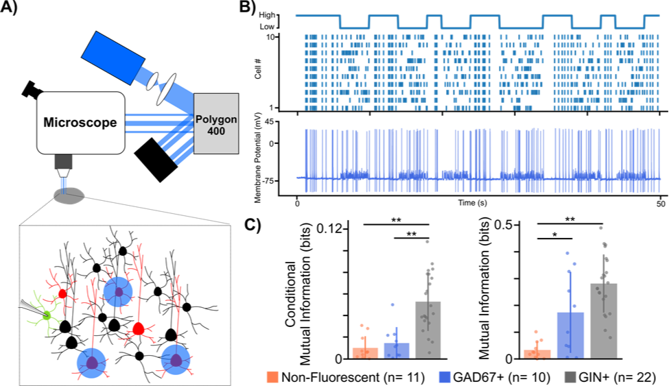
Figure 1. Using a digital micromirror device to study microcircuit multiplexing in the neocortex.
(A) Experimental set-up using digital micromirror device (Polygon, Mightex).
(B) Example trace from GAD67+ cell showing high mutual information to temporal code stimulation. Top: illustration of temporal protocol showing when a high or low temporal code (i.e. synchrony) is induced. Bottom: Example trace from GAD67+ cell to temporal protocol stimulation.
(C) Mutual information analysis of different cell type spiking responses to both rate (left) and temporal (right) codes. * p < 0.05, ** p < 0.001 Welch’s t-test with Bonferroni correction.
To test our hypothesis, we developed a novel experimental paradigm that biased the spiking patterns of pyramidal cell populations to convey either a rate or temporal code while electrical postsynaptic recordings from either one of two major interneuron types, somatostatin positive (SST+) or parvalbumin positive (PV+), were obtained. To carry out our experiments we used transgenic mouse lines (GAD67 and GIN), which express green fluorescent protein (GFP) in SST+ and PV+ interneurons respectively. We then virally expressed the optogenetic actuator Channelrhodopsin-2 (ChR2) in pyramidal cells found in anatomical layers 2/3 of the somatosensory cortex. After 3 weeks, to allow for sufficient viral expression, acute slices of the somatosensory cortex were prepared to allow for whole cell patch clamp recordings of GFP+ interneurons. Crucial to our experiments was the ability to optically stimulate different pyramidal cells at different times in order to bias them towards a rate or temporal code. To do this, we used a digital micromirror device (Polygon, Mightex) which allowed us to draw patterns around pyramidal cells we wished to stimulate (Fig 1A,B).
In order to analyze whether these different cell types were more or less sensitive to rate or temporal coding, using the signal we generated and the recorded cellular responses, we analyzed whether the recorded cell’s spiking carried any information about the signal. Mutual information analysis of the post-synaptic spiking responses to both rate and temporal protocols suggested that neocortical interneurons, on the whole, carry more information about rate and temporal coding than non-fluorescent control cells, a majority of which were excitatory pyramidal cells. Furthermore, it seemed that the postsynaptic spiking of SST+ cells carried more information about both rate and temporal codes, whereas spiking responses from PV+ cells only carried information about the temporal code when compared to controls. While our data is still preliminary, the fact that different subclasses of interneurons showed cell type specific differences to each coding regime suggests that interneuron diversity may indeed play an important role in the multiplexing of different spike codes in the brain. This is the first time that anyone has ever demonstrated this and was only possible thanks to our use of Mightex’s Polygon.
References:
1. Panzeri, Stefano, et al. “Sensory neural codes using multiplexed temporal scales.” Trends in Neurosciences 33.3 (2010): 111-120.
2. Andrási, Tibor, et al. “Differential excitatory control of 2 parallel basket cell networks in amygdala microcircuits.” PLoS Biology 15.5 (2017): e2001421.
3. Harvey, Michael A., et al. “Multiplexing stimulus information through rate and temporal codes in primate somatosensory cortex.” PLoS Biology 11.5 (2013): e1001558.
4. Zuo, Yanfang, et al. “Complementary contributions of spike timing and spike rate to perceptual decisions in rat S1 and S2 cortex.” Current Biology 25.3 (2015): 357-363.
5. Tremblay, Robin, Soohyun Lee, and Bernardo Rudy. “GABAergic interneurons in the neocortex: from cellular properties to circuits.” Neuron 91.2 (2016): 260-292.
Simultaneous Optogenetic Stimulation and Electrophysiology Recordings Using a Dual Camera Microscopic System(Application Note, 2018)
Introduction
Neuroscientists interested in studying the principles of information processing in different brain circuits often turn to experimental techniques that help map out how and which individual neurons communicate with each other. To generate these so-called “circuit maps”, appropriate stimulation and recording tools are necessary to provide both biologically relevant inputs and accurate readouts of the biophysical phenomena that are occurring. For example, whole cell patch clamp electrophysiology has been fundamental in expanding our understanding of neuronal communication and connectivity. This technique provides researchers with unmatched electrical resolution of both a cell’s intrinsic electrical characteristics as well as its responses to inputs from connected cells. In doing so, it remains the gold standard for researchers who seek to understand how neurons communicate with each other (Edwards et al., 1989; Markram & Tsodyks, 1996).
The development of light-sensitive genetically encoded protein actuators, known collectively as “optogenetic” proteins, have provided neuroscientists with the ability to control the activity of neurons with light. By harnessing optogenetics to turn specific neurons on or off, this technique has quickly become a staple in many labs for elucidating how different brain circuits composed of functionally heterogeneous cellular populations operate (Fenno et al., 2011).
Optogenetics provides researchers a method to manipulate neuronal activity with high temporal and genetic specificity. However, a key limitation of current optogenetic stimulation protocols is that most researchers cannot accurately control the spatial pattern of light on a slice (Packer et al., 2013) to stimulate spatially segregated axon terminals or individual neurons.
Recently, the use of digital micromirror devices (DMDs) for patterned illumination have provided a solution to this problem (Packer et al., 2013). DMDs are optical chips containing microscopic moveable mirrors arranged in a rectangular array with each mirror corresponding to 1 pixel within an image plane. When light is shone through said chip, each moveable mirror can be individually rotated into an on state or off state allowing for an arbitrary pattern of light to be projected onto the specimen plane (Zhu et al., 2012). Over the years, DMDs have been adopted as a reliable method for multisite optogenetic stimulation of different neurons and axon bundles across many different species (Andrási et al., 2017; Shimizu & Stopfer, 2017; Zhu et al., 2012). This is especially true for experiments utilizing ex vivo whole-cell electrophysiology, wherein light-sensitive neurons are stimulated through sectioned brain tissue instead of a whole brain mount, thus resulting in enhanced stimulation accuracy due to a reduction in light scattering normally seen in in vivo experiments (see Al-Juboori et al., 2013; Andrási et al., 2017; Butler et al., 2016).
The integration of patterned illumination to a traditional electrophysiology rig is quite straightforward with inexpensive and plug-and-play DMDs being commercially available. For example, commercial patterned illuminators, such as the Polygon developed by Mightex Systems, can create arbitrary patterns of light that are projected onto the specimen plane with various wavelengths of light. Nonetheless, there is still one major technical constraint that materializes when optimizing the functionality of such a system for circuit mapping experiments.
The success of reliably recording a neuron using patch-clamp electrophysiology is greatly improved when the researcher can be guided by visualization of the cells via a high magnification (40-60x) objective with an infrared (IR) sensitive camera. However, circuit mapping often requires low magnification objectives (≤5x) to activate spatially distant sites or large regions in a slice. Because DMD stimulation is done via a microscope’s objective, researchers engaged in visually guided patching are either restricted to stimulating with the same high magnification objective they use for patching, or manually switching the objective once a patch has been formed and they are ready to stimulate the slice. The difficulty with this is that the seal between the glass pipette and the cell’s plasma membrane is extremely sensitive to mechanical disruption, so changing or moving the objective lens greatly jeopardizes the quality of electrical recordings.
Thus, an electrophysiologist interested in mapping out the neural circuitry of a particular brain region using patterned stimulation is faced with a challenge: How can they engage in simultaneous visually guided patching at high magnification and optical stimulation at low magnification?
To reconcile this problem, our solution has been to use a magnification changer with dual camera ports (see Figure 1). This system sends the image from the objective to two different cameras with different lenses to alter the magnification. Ultimately, this setup allows us to simultaneously visualize cells using an IR sensitive camera at a high magnification all while producing a wide-field image of the slice using an inexpensive camera at a low magnification to properly stimulate spatially distant ROIs within the slice.
Setup
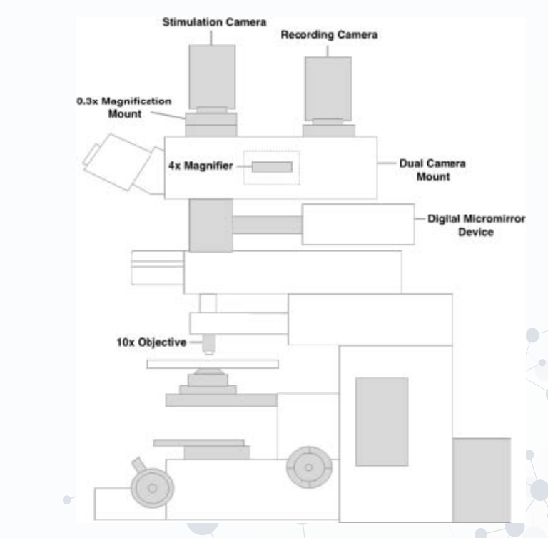
Figure 1. Schematic of dual camera port setup.
1. Stimulation Camera: We suggest utilizing a camera with a large sensor to capture a large field of view for stimulation.
2. Recording Camera: We suggest opting for a high-resolution, IR sensitive camera to properly visualize live neurons.
3. Dual Camera Mount: The dual camera mount must allow the two cameras to operate at different magnifications.
4. Digital Micromirror Device (DMD): We opted towards using the Polygon pattern illuminator because of its low cost, ease-of-use, and software allowing for design of arbitrary patterns of light based upon the camera image being captured.
5. 0.3x and 4x Magnifiers: (grey dotted box illustrates 4x magnifier built into dual camera mount).
6. Low-Mid Magnification Objective: We suggest purchasing an objective with mid-range magnification (10-20x) and high NA in order to generate high resolution images of the slice at high magnification.
Research Examples
As mentioned previously, the use of this system could aid neuroscientists interested in both intra and interregional circuit mapping within the brain. The adaption of this dual camera setup can provide researchers with the flexibility of studying how different anatomical regions are connected to one another (Fig. 2A). Furthermore, at a microcircuit level, researchers interested in a particular region of the brain can study how different cell types that are spatially distant (e.g. in different layers) are connected to each other (Fig. 2B). Those studying cellular biology can also utilize this setup to create an all-optical approach to study, for instance, organelle transport, and other protein-protein interactions at a single cellular level (Tischer & Weiner, 2014; van Bergeijk et al., 2015). In cases like organelle transport and protein displacement, researchers may instead require a high magnification to stimulate specific proteins, and a wide field of view to detect their movement across a sample.
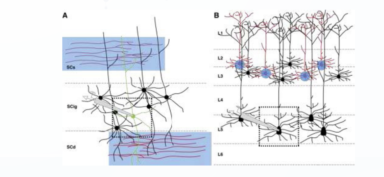
Figure 2. Graphical examples of macro and micro-circuit mapping using our dual camera set-up with patterned illumination.
(A) Macro-circuit dissection of sensory inputs coming into the different layers of the superior colliculus (SC). Light sensitive axon terminals (red) from the retina project to the superficial layer of the SC (SCs) while light sensitive axon terminals from somatosensory areas such as the barrel cortex project to the deeper layers of the SC (SCd). Electrical recordings from cells within the intermediate layer (SCig; green cell) during stimulation of both layers simultaneously would provide researchers with a better understanding of how neurons in the SC integrate multisensory information. Black dotted box indicates what would normally be seen at 40x. When compared to the 4x magnification, light stimulation of distant axon terminals would be almost non-existent under 40x.
(B) Micro-circuit dissection of L5 pyramidal cells within the cerebral cortex. With single cellular stimulation of light sensitive L2-3 pyramidal cells (red) researchers can study how excitatory inputs from L2/3 cells are integrated by L5 pyramidal cells. Similar to above, black dotted box indicates what would normally be seen at 40x. In this case only the soma of one cell would be accurately stimulated compared to the 4x.
Conclusions
While the advent of optogenetics has revolutionized how researchers study neural circuits, the spatial specificity provided by traditional stimulation techniques have often been found wanting. The recent development of low cost patterned illuminators such as Polygon have resolved this problem and, indeed, for an electrophysiologist interested in studying cellular responses to individual cells or segregated inputs from different regions of the brain, these systems are essential. In order to overcome the limitations of combining visually guided patch-clamping in conjunction with patterned stimulation, a dual camera setup on a microscope has proven to be effective. A plethora of stimulation paradigms, unique to patterned illumination, have become available to use through the implementation of this setup. This flexible configuration can help neuroscientists interested in studying how different neurons communicate across a wide range of circuits. In addition, though designed with the electrophysiologist in mind, this setup can be adapted by any researcher who wants to use light-sensitive actuators in their experiments.
References:
1. Al-Juboori, Saif I., et al. “Light scattering properties vary across different regions of the adult mouse brain.” PLoS One 8.7 (2013): e67626.
2. Andrási, Tibor, et al. “Differential excitatory control of 2 parallel basket cell networks in amygdala microcircuits.” PLoS Biology 15.5 (2017): e2001421.
3. Butler, James L., et al. “Intrinsic cornu ammonis area 1 theta-nested gamma oscillations induced by optogenetic theta frequency stimulation.” Journal of Neuroscience 36.15 (2016): 4155-4169.
4. Edwards, Frances A., et al. “A thin slice preparation for patch clamp recordings from neurones of the mammalian central nervous system.” Pflügers Archiv European Journal of Physiology 414.5 (1989): 600-612.
5. Fenno, Lief, Ofer Yizhar, and Karl Deisseroth. “The development and application of optogenetics.” Annual Review of Neuroscience 34 (2011).
6. Markram, Henry, and Misha Tsodyks. “Redistribution of synaptic efficacy between neocortical pyramidal neurons.” Nature 382.6594 (1996): 807.
7. Packer, Adam M., Botond Roska, and Michael Häusser. “Targeting neurons and photons for optogenetics.” Nature Neuroscience 16.7 (2013): 805-815.
8. Shimizu, Kazumichi, and Mark Stopfer. “A population of projection neurons that inhibits the lateral horn but excites the antennal lobe through chemical synapses in Drosophila.” Frontiers in Neural Circuits 11 (2017).
9. Tischer, Doug, and Orion D. Weiner. “Illuminating cell signalling with optogenetic tools.” Nature Reviews Molecular Cell Biology 15.8 (2014): 551.
10. van Bergeijk, Petra, et al. “Optogenetic control of organelle transport and positioning.” Nature 518.7537 (2015): 111.
11. Zhu, Peixin, et al. “High-resolution optical control of spatiotemporal neuronal activity patterns in zebrafish using a digital micromirror device.” Nature Protocols 7.7 (2012): 1410.
Demonstration of Single-Cell Optical Control with the Polygon Pattern Illuminator(Application Note, 2019)
Since the advent of optogenetics, many researchers have been working towards developing a method for single-cell optical control of multiple, individual neurons within a neural circuit. Such level of fidelity would allow neuroscientists to better understand how neurons can encode or decode information within the brain. Given that the Polygon can accurately generate arbitrary patterns of light using thousands of micromirrors, we sought to determine whether this system’s patterned illumination could allow for single cell optical control of cortical neurons ex vivo.
To first enable light-sensitivity within our cells, we virally transfected the neocortex of wild-type mice (C57Bl/6 mice) with a virus containing the transgene for channelrhodopsin-2 (hChR2(E123T/T159C)) and an mCherry fluorescent reporter under a calcium-calmodulin kinase II alpha (CamKii-a) promoter. In doing so, only excitatory pyramidal cell types would express ChR2 along with the mCherry fluorescent protein. After waiting 2-3 weeks for expression within the somatosensory cortex, we then recorded from these ChR2 expressing cells (Fig. 1A).
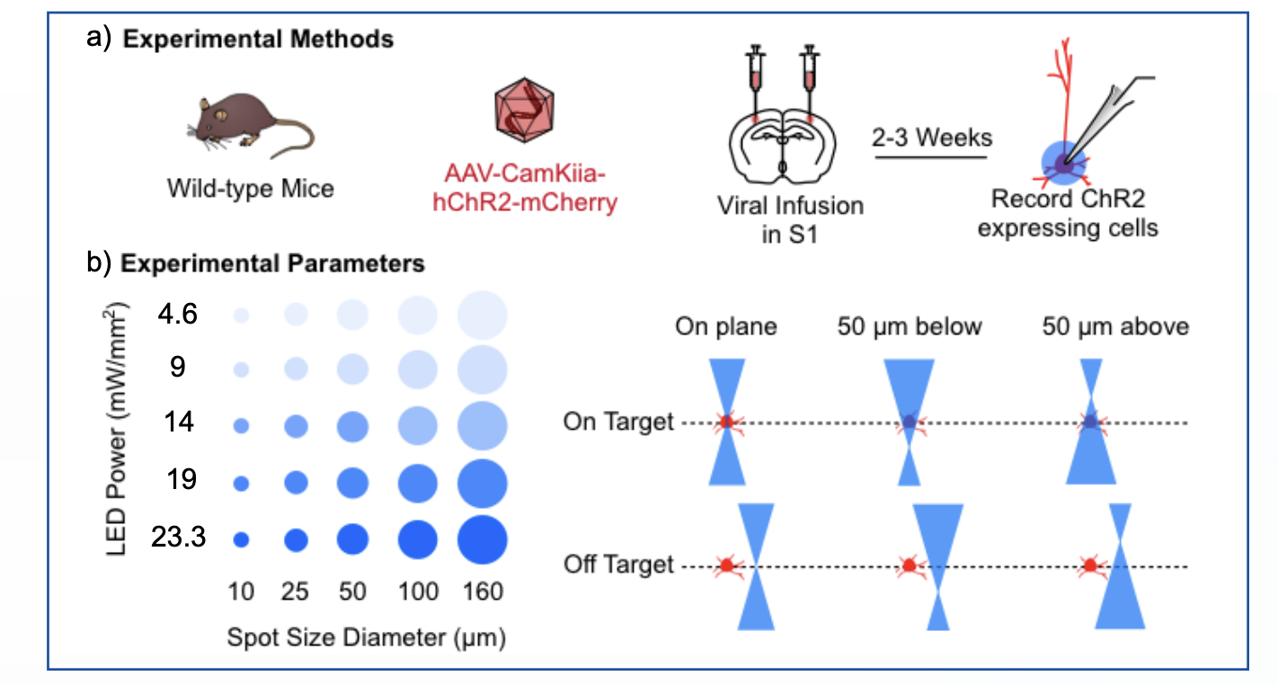
Figure 1. Experimental methods and parameters for single-cell optical control with the Polygon.
(A) Experimental methods.
(B) Experimental parameters: LED power and spot size diameter (left) and on-target / off-target stimulation conditions (right).
Next, to determine whether the Polygon could optically control single cells within the neocortex, we devised an experimental protocol to test how recorded cells responded to varying light intensities (mW/mm2) as well as spot sizes (μm) drawn directly on top of their cell bodies (Fig. 1B, left). While the Polygon can draw arbitrary patterns of light, allowing for tight regulation of light patterns in the xy plane, the system itself cannot control for light arriving above and below our neuron of interest. As such, given the cone of illumination that is produced during single-photon illumination, we generated two conditions: 1) an on-target condition whereby a spot was either directly on the same plane of the cell or 50 μm above or below and 2) an off-target condition whereby the spot was 50 μm above or below and 50 μm away in the xy plane (Fig. 1B, right). Thus, to determine what parameters would elicit single-cell optical control, we would optimize for the LED light intensity and spot size diameter that produced both the highest likelihood of spiking during on-target stimulation as well as the lowest likelihood of spiking during off-target stimulations.
As evidenced in the sample traces, cells within the on-target condition often showed increases in excitability when either the spot size or LED intensity increased (Fig. 2A, left). This was not the case within the off-target condition, whereby some cells required at least 80% light intensity to exhibit noticeable depolarizations (Fig. 2A, right).
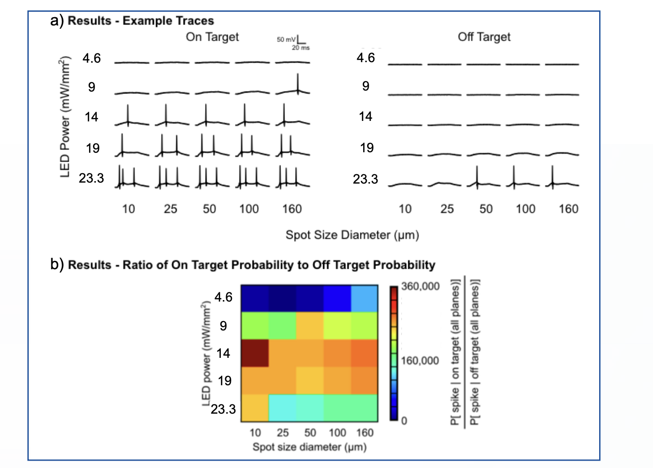
Figure 2. Results of single-cell optical control with the Polygon.
(A) Results – example traces for on-target (left) and off-target (right) stimulation.
(B) Results – ratio of on-target to off-target spiking probability across LED power and spot size diameter.
To determine what LED intensity and spot size diameter would produce both the highest likelihood of spiking during on-target stimulations and the lowest likelihood of spiking during off-target stimulations, we sought to calculate a ratio of these probabilities (Fig. 2B). Based upon preliminary data, this work seems to demonstrate that with a spot diameter of 10 μm and LED power of 14 mW/mm2 the Polygon can elicit spiking in a targeted cell with 360,000 times greater probability than in a non-targeted cell 50 μm away. Therefore, with our setup and the appropriate virus titration (to ensure sparse infection of ChR2), the Polygon enables single-cell resolution optical control in ex vivo brain slices.